Lets dig into the details! 
MCU compatibility
The target must be a 32-bit MCU which uses Intel format (LSB – Least Significant Byte first) which is the vast majority of the MCU. Floating point capability is recommended but not necessary.
Non-Volatile Memory (NMV) is needed to store data between power cycles. It can be any type of storage that can be read/written in real-time e.g. emulated EEPROM in flash or external EEPROM.
CAN
CAN (Controller Area Network) is a popular communication protocol to send data between control units (ECUs) and is used by the other protocols e.g. UDS, XCP and CANopen.
CAN messages and its signals to be transmitted or received are easily configured with a GUI. Up to 4 CAN channels are supported ant it is possible to configure a receive messages to transmitted on the other CAN channels (gateway functionality).
CAN FD with up to 64 bytes payload and 8 MBit baud-rate is supported as well.

Generated DBC file
During the build a DBC file is generated which contains all messages and signals. DBC file is commonly used by tools who needs to monitor the CAN bus traffic.
Diagnostic
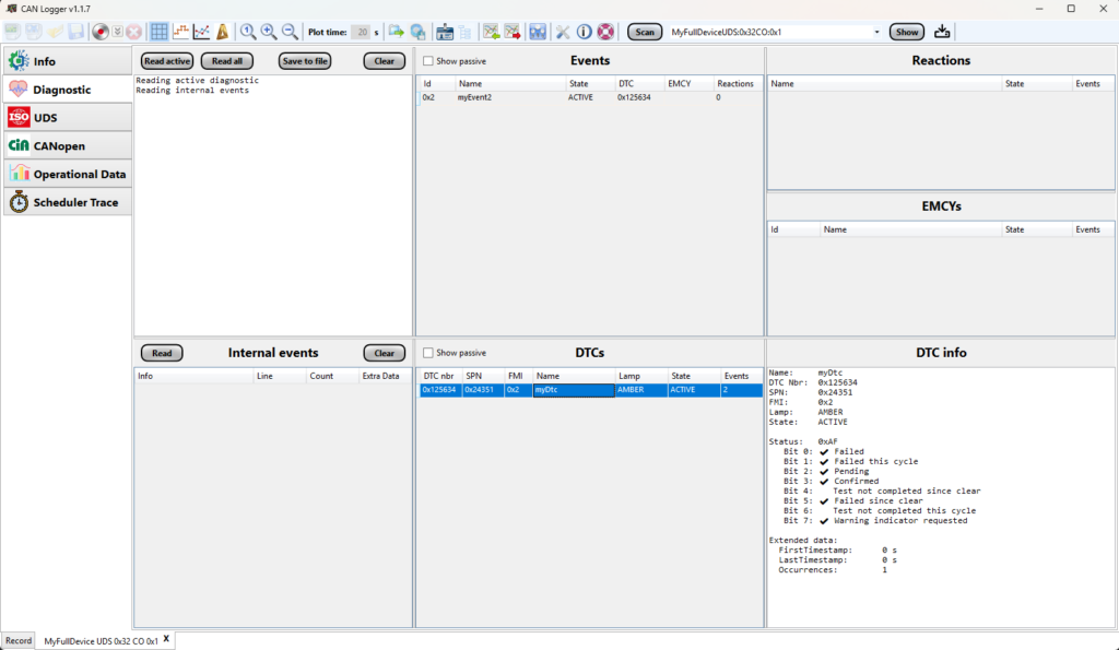
Diagnostic of e.g. sensors and actuators are an important part of en embedded system. If an error has been detected it can report it to the diagnostic engine which will set an event to be active. Each event can be connected to an reaction which e.g. disables an actuator or limit the maximum power.
Events can also be connected to DTCs (Diagnostic Trouble Codes) for UDS/J1939 protocol or to EMCY (Emergency messages) for CANopen protocol. For DTC, extended data and snapshot (Freeze frames) can be stored as well.
Internal event stores information of software bugs e.g. if ended up in default state of switch/case or receives a null pointer.
All diagnostic information can be read with CAN Logger or by other UDS/CANopen compliant tools.
NVM – Non-Volatile Memory
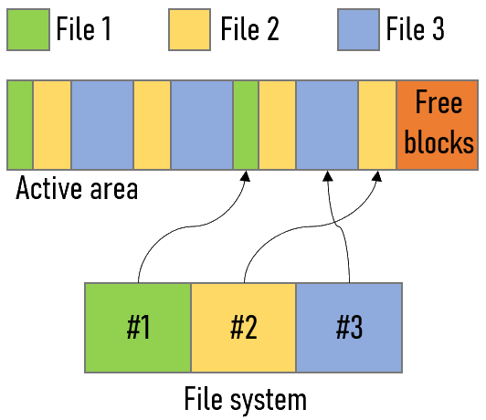
The purpose of the NVM handler is to handle persistent storage so the data will be kept between power cycles or resets. Multiple sets of persistent data can be stored, and each set is referred as a “file” as the NVM handler basically are a file system which holds information about all files in the system.
At start-up the file system is created and all files RAM mirror are filled with EEPROM data if OK or default value if corrupt or missing. Save to EEPROM/FLASH can be done on request or at shutdown of the system. The actual storage to EEPROM/FLASH (erase, read and write) is done outside the platform and the data can be stored in any possible memory such as FLASH, EEPROM, eMMC or SD card.
The NVM storage memory is divided into two equal areas. One area will be the active area and files will be stored to it, which means that it can hold several versions of each file. The file system keeps track of where the latest file version is stored. When the active area is full the latest version of each file will be copied to the other area which then will be the active one. For extra sensitive data the file can be stored in two places for redundancy.
UDS – Unified Diagnostic Services
The UDS protocol (Unified Diagnostic Services) is an ISO standard specified in ISO-14229 and contains a set of services which can be used for diagnostic purposes.
UDS are designed to be used on different communication interfaces like CAN and Ethernet, but only CAN is supported in this implementation.
A UDS Tool (normally on PC) can be used to read out information on ECUs via the CAN bus. Each ECU implements a UDS server which a UDS client/tester (UDS tool) can connect to. Both the clients and the servers have assigned a specific UDS source address (0-254) which will be part of the CAN ID when transmitting messages. The UDS client can either communicate directly with a single UDS server by using its UDS source address in the CAN message ID. This is called physical addressing. It can also communicate with all ECUs by broadcasting to everyone, which is called functional addressing. UDS uses extended CAN frames (29 bits identifier) where last byte is the source address of the transmitting node and the second last is the targeted UDS node’s source address (set to 0xFF if functional addressing).
All communication are request/response based which means that the client will send a request of a service and the client(s) will respond to the request.
Each UDS server can have different sessions which supports a set of services. When starting it will be in Default session (1) and to change session the Diagnostic Session Control service (0x10) are used. The extra sessions according to the standard are e.g. Programming session (2) and Extended Diagnostic session (3) but others can be used if needed. The services that is present in Default session must also be present in all the other sessions! If a non-default session is active the Tester Present service (0x3E) must be used at least every session timeout by the client who requested the session otherwise it will go back to the default session.
To protect services and parts of services like DIDs and routines a number of security levels can be used. To activate a security level the Security Access service (0x27) are used which uses a seed and key mechanism. Security levels can only be used in non-default sessions and when switching to another session the security level will be reset.
The UDS server can handle up to 3 separate UDS clients simultaneously and each of them have a separate security level. If a client is requesting a non-default session then that client must ensure to send Tester Present to keep it alive, the other clients Tester Present will be ignored! Since the session is shared between all clients it means that a session change will reset all connected clients security level.
If CAN FD is used for the CAN channel then is is configurable if UDS shall use up to 64 bytes payload or use the classic 8 bytes.
| ID | Name | Supported |
|---|---|---|
| 0x10 | Diagnostic Session Control |  |
| 0x11 | ECU Reset | |
| 0x14 | Clear Diagnostic Information | |
| 0x19 | Read DTC Information | |
| 0x22 | Read Data By Identifier | |
| 0x23 | Read Memory By Address | |
| 0x24 | Read Scaling Data By Identifier | |
| 0x27 | Security Access | |
| 0x28 | Communication Control | |
| 0x2A | Read Data By Periodic Identifier | |
| 0x2C | Dynamically Define Data Identifier | |
| 0x2E | Write Data By Identifier | |
| 0x2F | Input/Output Control By Identifier | |
| 0x31 | Routine Control | |
| 0x34 | Request Download | |
| 0x35 | Request Upload | |
| 0x36 | Transfer Data | |
| 0x37 | Request Transfer Exit | |
| 0x38 | Request File Transfer | |
| 0x3D | Write Memory By Address | |
| 0x3E | Tester Present | |
| 0x84 | Secured Data Transmission | |
| 0x85 | Control DTC Setting | |
| 0x86 | Response On Event | |
| 0x87 | Link Control |

Need another service?
Support for another service can be added on request.
Supported Sub-functions
Some services has sub-functions. Contact us to get information about which one is supported!
J1939
J1939 is a SAE standard based which uses the CAN bus to transfer data. It uses 29-bits identifier and normally sends data at 250 or 500 kBit/s. J1939 is used in heavy-duty vehicles like trucks and buses and specifies which CAN messages and signals should be transmitted from different ECUs.
The following J1939 features are supported:
- DM1 (active DTCs + lamp status) continuously every 1 second
- DM2 (passive DTCs + lamp status) on request
- DM3 (clear passive DTCs) on request
- DM4 (Freeze frame data) on request
- DM11 (clear passive DTCs) on request
- BAM messages (broadcast messages split up in multiple CAN frames if >8 bytes of data)
- Unsupported PGNs can be handled by application if needed
Future extensions
- Address claim
- Peer-to-peer communication (multi-frame)
Handling of J1939 messages/signals?
J1939 specified messages/signals with PGN/SPN according to J1939 DA (Digital Annex) are handled as any other CAN message/signal and is specified in the configuration tool, which has built-in support to handle ERROR and/or NOT AVAILABLE for J1939 signals.
CANopen
The CANopen standard is useful as it enables off-the-shelf interoperability between devices (nodes) in e.g. industrial machinery, robotics and medical devices. Each slave device is assigned a CANopen node ID (1-127) and a master can control one or several devices.
The following CANopen features are supported:
- NMT – Network Management (slave device)
- SYNC – Sync message
- EMCY – Emergency
- SDO – Service Data Object
- PDO – Process Data Object (dynamic configurable)
- HEARTBEAT – Heartbeat message
- TIME – Time message
- Object Dictionary (OD) – exported in EDS format
Programming with CANopen?
Sample implementation of programming via CANopen SDO is including in the software package.
Connect multiple tools to a device?
To be able to both be controlled by a CANopen master and to log data with SDO by e.g. a PC tool, a device can have up to 4 additional node IDs. These node IDs can only be used for reading/writing Object Dictionary (OD) entries with SDOs.
XCP
XCP (Universal Measurement and Calibration Protocol) is a network protocol originating from ASAM for logging and calibrating ECUs. It gives read and write access to variables and memory contents of ECUs/devices at runtime.
XCP is designed to work work on several communication buses e.g. CAN, ethernet, SPI and USB. CREP supports CAN and ethernet (UDP/IP) where ethernet is much faster (10-100 MBit). The same CAN bus but can be used for XCP and other protocols at the same time which makes the use of CAN bus for XCP the most used.
The XCP protocol are purely working with addresses and are not aware of which variables or parameters are located at the used addresses. When we do measurement and calibration from an ECU we would like to work with the names of the variable and not the addresses since they will move around for different software releases. To overcome this problem another ASAM standard is used, the A2L file. An A2L file is generated during the build and holds information about variables and parameters in the ECU. Which variables/parameters to be included in the A2L file is specified in separate files and specified at least its name. During the build each variable’s datatype, address and size is extracted from the debug information, which makes it easy to add new variables/parameters.
If CAN FD is used for the CAN channel then is is configurable if XCP shall use up to 64 bytes payload or use the classic 8 bytes.
| Functionality | Supported |
|---|---|
| Upload of value from ECU by polling | |
| Download a value to ECU | |
| DAQ: Continuous read of values in ECU | |
| Support for multiple DAQs with different period times | |
| Ensure only available memory addresses are used | |
| Possibility to enable or disable the protocol | |
| Possibility to make XCP read-only | |
| STIM: Continuous write of values in ECU (bypassing) | |
| Possibility to use seed&key to protect the usage of XCP | |
| Programming/Flashing | |
| Multiple calibration pages and switch between them |
Operational data
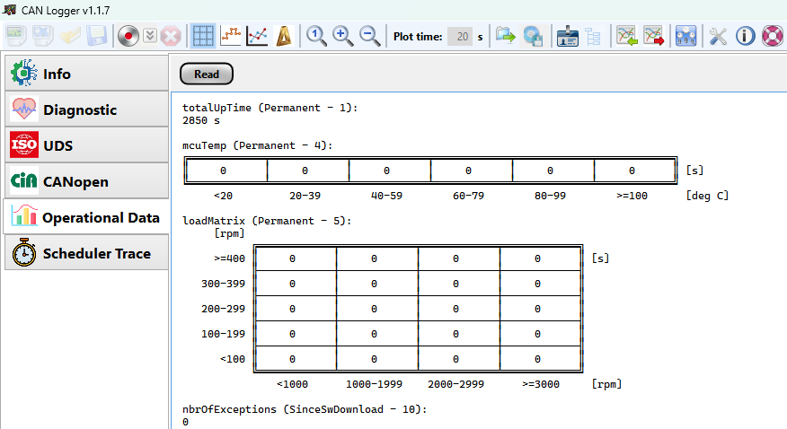
Operational data keeps track of shows how the system has been used during its lifetime (or since last cleared). It can handle scalar values, arrays (histogram) and matrices. The operational data is stored in NVM and can use multiple files. This enables to add some operational data in a file that never will be erased and some in a file that will be erased at every software update.
Each operational data item can be scaled and have units. Histograms and matrices have axes with specified units. The operational data can be read with XCP, UDS or CANopen and CAN Logger can visualize it in understandable format.
Scheduler
The scheduler handles the execution of functions in correct order and at specified frequency. A task is a set of functions to execute in specified order when it is triggered. Normally the tasks are periodic and triggered by a timer, but they can also be triggered on specific events such as a button is pressed.
The scheduler is minimalistic but therefore also very efficient. The scheduler is optional to use and can be replaced with the RTOS/scheduler of your liking.
Each task is assigned a priority and a higher priority task can interrupt a lower priority task. The lower priority task will then resume its execution when no higher tasks needs to be executed
It is possible to visualize the task’s functions execution with CAN Logger. Very useful to see that tasks has correct priorities and to measure functions execution times.
Use of software interrupts
To not use too many timers for the scheduler it is possible to use software interrupts instead to trigger a task. They can be used if the task’s period time is a multiple of another tasks driven by a timer. For example if you have a timer task running at 1 ms then you can use software interrupts to trigger a 10 ms task.
Task execution monitoring
Each task is measuring its execution time and also keeps track of the maximum execution time. These can be read with XCP and is expressed as % of its specified period time.

Boot loader
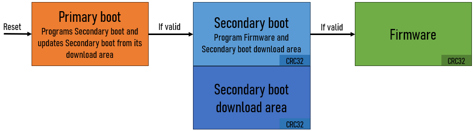
The boot is the software part that is executed first when the ECU starts. Its responsibility is to start the Firmware/Application if it is valid and also to update the Firmware in the field.
To ensure that it is valid it calculates a checksum of its flash area and compares it to a checksum stored at specific flash address. Sometimes it is necessary to update the boot loader itself. If a power loss or communication failure occurs during the update of the boot it can cause a bricked unit which can be hard to fix in the field. To remove the risk of bricked units a double step boot loader can be used. A primary boot loader will be static on the unit for its lifetime. Its only responsibility is to start the secondary boot loader if valid and to be able to update it if not valid.
The primary boot loader shall be very simple since the end user will never see it. The secondary boot loader can be more advanced with e.g. possibility to read DTCs and internal events. It also handles the programming of the Firmware and the update of itself if needed.
To be able to update secondary boot loader it will write the program code to a separate download area. When that is done it do a reset and the primary boot will see that a new secondary boot exists in the download area and program it to the real Secondary boot area.
Programming protocols
The boot is not limited to a specific set of programming protocols. The CREP platform will be delivered with example to program with UDS and CANopen but it can be extended to other protocols as well.
Build system
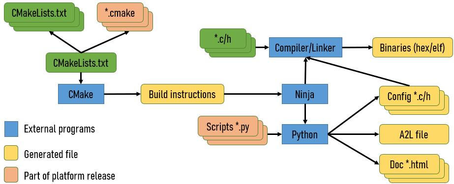
The platform is delivered as a pre-built library (*.a) together with a set of header files which specified how to interact with the platform. The application code is compiled and then linked together with the library to get the final binary which can be programmed on the embedded processor.
There are a bunch of tools and scripts that needs to be called before or after the build and to simplify all these steps a build system can be used. The platform is delivered with a simple build system using CMake and Ninja.
CMake is a well known high level build system. What to build and which dependencies the build artifacts have is specified in CMakeLists.txt and *.cmake files. The output from CMake is a build instruction which specifies all the commands to execute and in which order. Ninja is a low level build system which takes the build instruction and executes them.
The build system is designed to be easy to extend and adapt.
Build steps
- Generate code for configuration before Building
- Generate A2L file to be able to debug with XCP
- Modify HEX file with checksum
- Generate documentation for the build